ESP32 ADC
Introduction to ADC functions, and Joystick, Thermistor, Photoresistor, Gas sensors (MQ-2, MQ-3, MQ-135), eNose.
ADC (Analog Digital Converter)

Vin is input voltage for ADC to sample
Vref is reference voltage for ADC to compare with Vin
3-bit ADC example:

12-bit ADC : output is a 12-bit binary code, so its value = 0 ~ 4095

ADC architecture
Direct-Conversion ADC

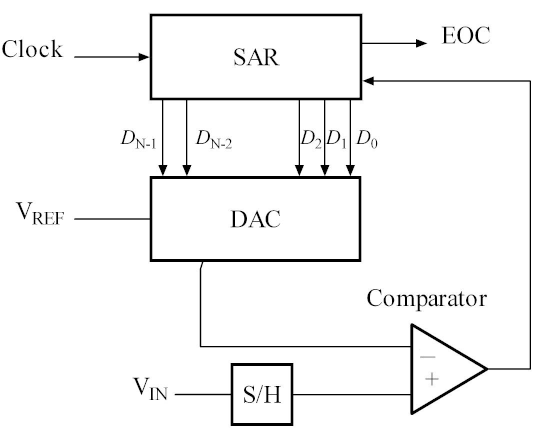
Successive-Approximation ADC
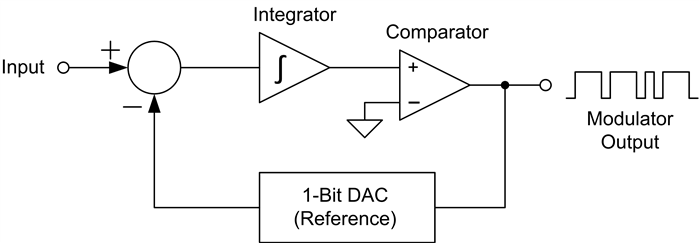
Sigma-Delta ADC
ESP32 ADC
Analog Input Tutorial
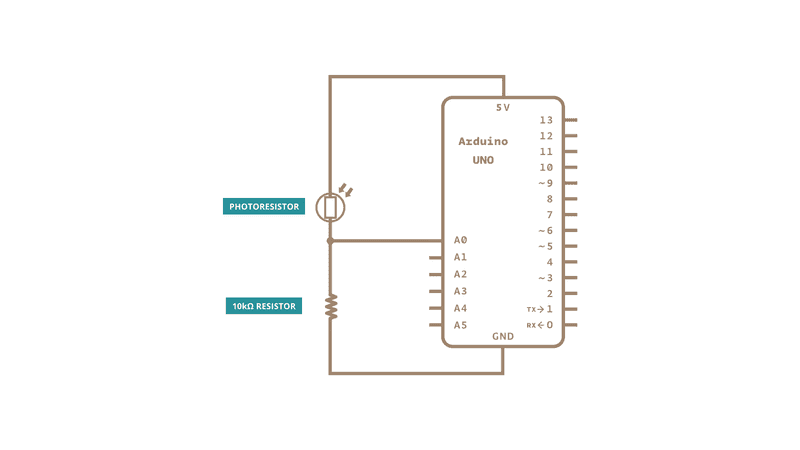
Vout = Vin * R2 / (R1+R2)
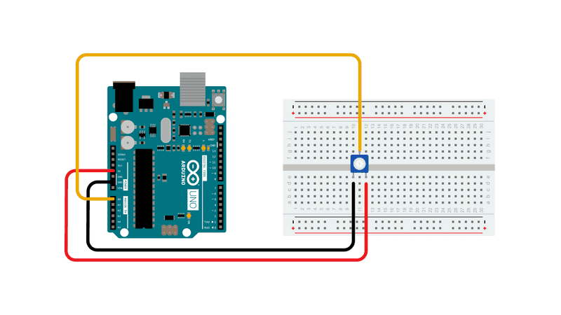
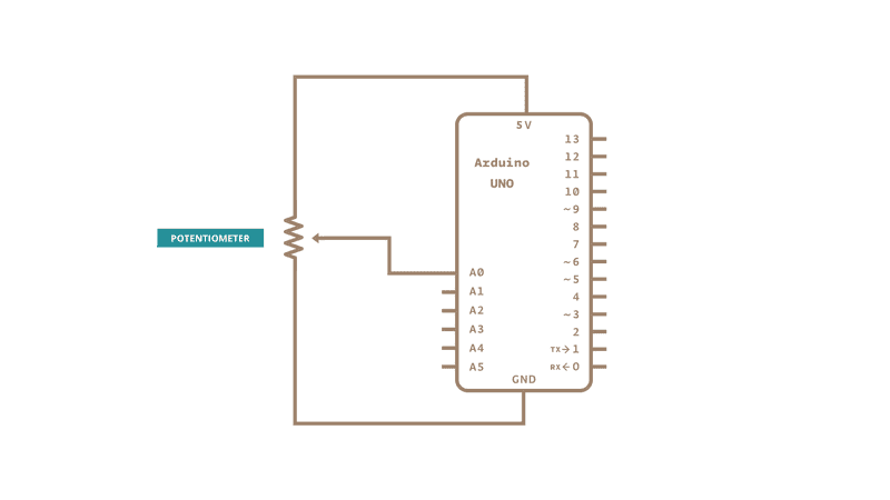
With a potentiometer
 |
 |
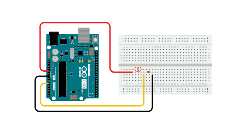
With a photoresistor
 |
 |
NodeMCU-32S pinout

Sketch> ESP32> ESP32_ADC
- Connect NodeMCU-32S with a NTC-Thermistor and a 10K ohm to GND

- Download ESP32_ADC.ino
to ~/Documents/Arduino/examples/

- Verify, then Tools>Serial Monitor>

Sketch> ESP32 > ESP32_ADC_Joystick

Examples> 03.Analog>
-
AnalogInOutSerial - Read an analog input pin, map the result, and then use that data to dim or brighten an LED.
-
AnalogWriteMega - Fade 12 LEDs on and off, one by one, using an Arduino Mega board.
-
Calibration - Define a maximum and minimum for expected analog sensor values.
-
Fading - Use an analog output (PWM pin) to fade an LED.
-
Smoothing - Smooth multiple readings of an analog input.
Examples> 03.Analog> AnalogInput
- Connect NodeMCU-32S with a NTC-Thermistor and a 10K ohm pulldown.

- AnalogInput.ino read sensor value as delay to turn LED on & off
- To show sensorValue
- setup() to add `Serial.begin(9600);
- loop() to add
Serial.println(sensorValue);
- Verify, then Tools>Serial Monitor>

Examples> 03.Analog> AnalogInOutSerial
-
Connect NodeMCU-32S with a NTC Thermistor and a 10K ohm pulldown.

-
Modify AnalogInOutSerial.ino
- analogOutPin = 2
- replace analogWrite to ledcWrite (for ESP32 PWM)
const byte ledPin = 2;  // for ESP32 built-in LED

// setting PWM properties
const int freq = 5000;
const int ledChannel = 0;
const int resolution = 10; //Resolution 8, 10, 12, 15

ledcSetup(ledChannel, freq, resolution); // configure LED PWM functionalitites
ledcAttachPin(analogOutPin, ledChannel); // attach the channel to the GPIO2 to be controlled

ledcWrite(ledChannel, 102); //PWM Value varries from 0 to 1023
-
Compile

-
Verify, then Tools>Serial Monitor>

NTC Thermistor
Negative Temperature Coefficient = Rising Temperature will decrease Resistance
NTC thermistors can also be characterised with the B (or β) parameter equation,
where the temperatures and the B parameter are in kelvins, and R0 is the resistance at temperature T0 (25 °C = 298.15 K).
Solving for R yields
取log
log(R) = log(R0) + B * (1/T – 1/T0)
1/T = 1/T0 + (log(R) – log(R0)) / B
T = 1 / (1/T0 + (log(R) – log(R0)) /B)
[Homework] Thermistor.ino
- write above formula in C++
- create Thermistor.ino with the following codes
Read ADC (get ADCvalue)
int16_t ADCvalue;

void setup(){
  Serial.begin(9600);
}

void loop() {
  ADCvalue = analogRead(A0);
  Thermistor(ADCvalue);
}
Read Thermistor (use ADCvalue to calculate R & T)
void Thermistor(int16_t ADCvalue)
{
  double T, Temp;
  double T0 = 301.15;  // 273.15 + 28 (room temperature) 室溫換成絕對溫度
  double lnR;
  int16_t R;          // Thermistor resistence
  int16_t R0 = 8805;  // calibrated by reading R at room temperature (=28 degree Celsius )
  int16_t B  = 3950;
  int16_t Pullup = 9930; // 10K ohm

  // R / (Pullup + R)   = adc / 4096
  R = (Pullup * ADCvalue) / (4096 - ADCvalue);

  // B = (log(R) - log(R0)) / (1/T - 1/T0)
  T = 1 / (1/T0 + (log(R)-log(R0)) / B );
  Temp = T - 273.15;

  Serial.println(Temp);
}
[Homework] Thermistor_accuracy.ino
- Create Thermistor_accuracy.ino
- Verify on NodeMCU-32S and, compare it to Thermistor.ino output
From Sketch/ESP32_ADC.ino
V = ReadVoltage(A0); //accuracy improved
double ReadVoltage(byte pin){
  double reading = analogRead(pin); // Reference voltage is 3v3 so maximum reading is 3v3 = 4095 in range 0 to 4095
  if(reading < 1 || reading > 4095) return 0;
  // return -0.000000000009824 * pow(reading,3) + 0.000000016557283 * pow(reading,2) + 0.000854596860691 * reading + 0.065440348345433;
  return -0.000000000000016 * pow(reading,4) + 0.000000000118171 * pow(reading,3)- 0.000000301211691 * pow(reading,2)+ 0.001109019271794 * reading + 0.034143524634089;
} // Added an improved polynomial, use either, comment out as required
Then,
V / 5 = R / (10K + R)
V = 5 * R / (10000+R)
V * (10000 + R) = 5 * R
10000 * V = 5 * R - V * R
10000 * V = (5 - V) * R
R = 10000 * V / (5-V)
V = ReadVoltage(A0); // ADC accuracy improved for ESP32
R = 9990 * V / (5 - V); // assuming 9990 is the measured resistance of 10K resistor by a multi-meter.
T = 1 / (1/T0 + (log(R)-log(R0)) / B ); // R0=8805 measured in room tempature at 28 celsius degree.
Temp = T - 273.15;

Serial.println(Temp);
Photoresistor

LDR arduino library
Photocell (Light Dependent Resistor) Library for Arduino
Sketchbook> GL5516>

- Download files from github.com/rkuo2000/arduino/examples/GL5516
- GL5516.ino
- LightDependentResistor.cpp
- LightDependentResistor.h

- Verify with NodeMCU-32S, and open Serial Monitor on ArduinoIDE

MQ Gas sensors


MQ2 300~10000ppm 煙幕感應器 (液化氧、丁烷、丙烷、甲烷、酒精、氫氣)
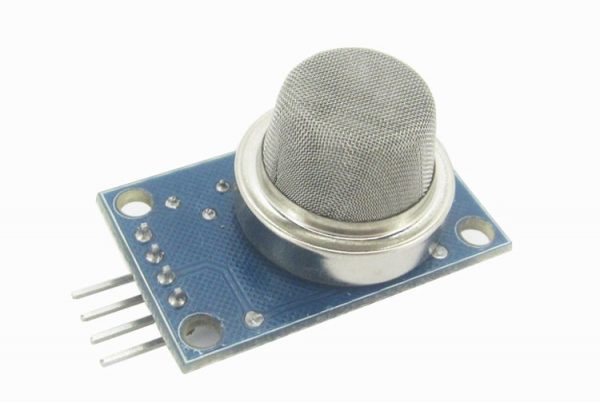 接線方式:VCC:接電源正極(5V)、GND:接電源負極、DO:TTL開關信號輸出、AO:模擬信號輸出
注意:感測器通電後,需要預熱20秒左右,測量的數據才穩定,感測器發熱屬於正常現象,因為內部有電熱絲,如果燙手就不正常了
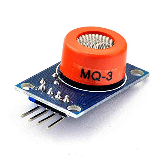
MQ3 酒精蒸氣,乙醇,氣體檢測模組
- The typical sensitivity characteristics of the MQ-3 for several gases. in their: Temp: 20°C、 Humidity: 65%、 O2 concentration 21% RL=200kΩ
- Ro: sensor resistance at 0.4mg/L of Alcohol in the clean air.
- Rs:sensor resistance at various concentrations of gases.
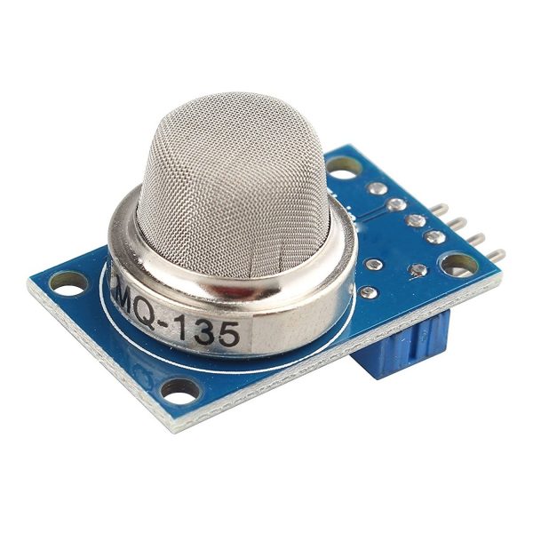
MQ-135 空氣品質檢測 有害氣體感測器模組
用於建築物/辦公室的空氣質量控制設備,適用於檢測NH3,NOx,酒精,苯,煙,CO2等。
Sketch> MQ3>
- NodeMCU-32 GPIO36(A0) is connected to MQ3 sensor AO pin
 |
 |
-
MQ3 Vcc connected to 5V, required 15 minutes burn-in

-
Open Tools>Serial-Monitor>

-
Open Tools>Serial-Plotter> to see waveform

-
3 test cases: Fresh Air, Your Breathe, Marker are applied to MQ3 sensor

Electronic Nose
Detection of Fruits in Warehouse
Paper: Detection of fruits in warehouse using Electronic nose

Estimating Gas Concentration
Paper: Estimating Gas Concentration using Artificial Neural Network for Electronic Nose

This site was last updated June 18, 2023.


